Difference between revisions of "Frequently Asked Questions (DIY FAQ)"
(→DEBUGGING) |
(→POPS) |
||
| Line 1,010: | Line 1,010: | ||
: See the power supply switch in the Neutron filter at GEO or at GGG, or see the positive 9V switch in [http://geofex.com/FX_images/oaspltr.gif] for how to hook up the PNP. | : See the power supply switch in the Neutron filter at GEO or at GGG, or see the positive 9V switch in [http://geofex.com/FX_images/oaspltr.gif] for how to hook up the PNP. | ||
| + | |||
| + | ''' Measure for DC ''' | ||
| + | |||
| + | [http://www.diystompboxes.com/smfforum/index.php?topic=69693.0 See this thread] | ||
== PEDAL SPECIFIC == | == PEDAL SPECIFIC == | ||
Revision as of 20:37, 30 July 2008
DIY Stompbox FAQ.
Copyright 2006 by Aron Nelson, All Rights Reserved.
Here is info to help you get around problems I had when I was starting out...
SKILLS you need to build your own stompboxes.
Already built a pedal, but it has problems?
Wondering what part does what?
QUESTIONS??? Join us in the DIY Stompbox Forum
Contents
- 1 GROUND
- 2 POTS
- 3 CAPACITORS
- 4 POWER SUPPLY
- 5 JACKS
- 6 TRUE BYPASS AND SWITCHING
- 7 DIODES
- 8 TRANSISTORS
- 9 RESISTORS
- 10 OP AMP
- 11 WIRE
- 12 ORDERING
- 13 ENCLOSURES
- 14 MEASUREMENTS
- 15 COMMON WORDS AND TERMS
- 16 CALCULATIONS/FORMULAS
- 17 DEBUGGING
- 18 POPS
- 19 PEDAL SPECIFIC
- 20 TOOLS
- 21 MISC
- 22 MISC LINKS
- 23 SOFTWARE
- 24 DESCRIPTIONS/SOUNDS
- 25 THE FORUM
GROUND
What is that upside-down triangle - is that ground?

Yes, it is ground.
Where do the connections that show a ground symbol go to?
Generally speaking, take all the ground points, connect them together, then connect them to the ground lug of the input or output jack. Take the power supply (i.e. battery) and connect it to the ground lug as well. If you want the input jack to switch your battery on and off, then connect the lug to ground as before, but connect the battery terminal to the middle connector (i.e. "ring")of a stereo jack. When a mono plug is inserted, the ground circuit will be complete and the switch will be on. Note that some circuits connect the + or positive terminal of the battery to ground (positive ground circuit), although it is more common to connect the negative terminal to ground. The sleeves of the input and output jacks usually go to ground as they are usually connected to the metal casing and the ground lug - unless they are isolated jacks (in which case you need to ground both jack sleeves with a ground wire). In general, metal jacks are not isolated from metal enclosures. If your box is painted you might consider scraping off some paint so the jacks can make contact with the metal on the box so the box can act as a shield; lock washers may do this as well.
POTS
Pots - How do I wire pots?
Apparently there's a standard for the terminals. When looking at the back of the pot (side opposite the shaft sticking out) with the terminals facing left, from top to bottom they are labeled 3,2 and 1. The terminals correspond to the schematic terminal wires.
When viewed from the front, a pot turned fully clockwise connects terminal 2 to terminal 3. Fully counterclockwise connects terminal 2 to terminal 1.Anyway, I know I have connected pots like this but they were still backwards. If that happens, simply swap the wires connected to terminals 3 and 1.
Pots - When do I use audio or linear taper pots?
You can use either one at any time. The taper may not be as optimum on some applications. The basic rule of thumb is use audio for volume and sometimes drive, use linear for everything else. That being said, you can use linear for everything. Linear pots will always "work". You can also turn a linear pot into a psuedo audio pot - read the next question.
Pots - What is the difference between linear and log or audio taper and how do pots work?
Check out the Secret Life of Pots at GEO.
Pots - I'm looking at a pot with the stem pointing at me. On the left side there is this little metal bit that sticks up. Why is that there?
From Joe Gagan: Some electronics manufacturers cast or drill a little hole in their enclosure to receive that tab on the pot as an additional anti-spin technology. You can either add that hole yourself, or break off the little tab with some pliers like most of us around here do.
Pots - How can I test a pot to see if it's linear or log taper?
From paul perry (Frostwave):Just put the shaft to half way. If it is linear, then it should measure the same value each way to the ends.(from wiper/middle to each outer lug) If not, it is log.
CAPACITORS
Here is a picture of various types of capacitors. Picture courtesy of Brad Fajardo
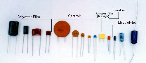
The most common types are Ceramic(they are cheap and generally used for small values), PolyesterFilm (common at Radio Shack) and Electrolytic. The other typescan be used but are more expensive. Electrolytics are polarized;i.e. they have positive and negative terminals, just like a battery.
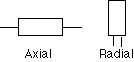
There are two very common packages of electrolytics that you will run into; Axial and Radial. As you can see below, the difference is where the leads exit the capacitor. I like Radials because they take up less space on the board.
This is what a typical electrolytic capacitor looks like. The side shown is the NEGATIVE side of the electrolytic. I have read in books that the the positive side is sometimes marked, but so far I have only seen the negative side marked in the capacitors I buy in the local stores.
 Radial capacitor with negative side showing.
Note the 16V on the electrolytic, this is the voltage rating of the capacitor. For our stompboxes,16V or 35V or anywhere in between is fine,. When you shop around, try and get the cheapest capacitor in this range. Sometimes the 35V will be cheaper than the 16V. Save money and buy the less expensive one.You can use any voltage capacitor as long as the voltage of the circuit you are using doesn't exceed the voltage rating. As long as you can fit the capacitor and the voltage rating is fine, you can use it.
Here are some common electrolytic symbols that you may encounter. In the following example, the negative lead would be facing down and the positive lead facing up.
Here's a link to a page that describes how to read capacitor values. Here's more about capacitors.
As usual, R.G.posted a great explanation about the subjective world of capacitors:
Also check out the sound of capacitors.
What's inside a capacitor? Also check out this page of dissected caps!
Here's a page of links re: capacitors.
Capacitors (AKA Cap)- What kind of capacitors should I use?
In a nutshell, you should use electrolytic when the capacitor is polarized. You can also use tantalum capacitors instead of electrolytic, but these are not commonly used. For any others, the basic consensus is to use film caps if they fit, otherwise use a mixture of film and ceramic capacitors. For most of our circuits, use caps with a minimum 16 volt rating. R.G. posted a great explanation about the subjective world of capacitors. For distortion circuits, others have noted that cheap ceramics sound good too, so use your ears! In general, 1uF and up will be electrolytic, any smaller values up to .001uF can be film types and picofarad values like 10pf-470pf are usually ceramic types. This is usually due to size, cost and availability. With the exception of elecrolytic and tantalum capacitors, most capacitors such as film or ceramic are non-polarized (often labeled NP). The orientation of a non-polarized capacitor doesn't matter; there's no positive or negative.
An interesting point to consider is that most vintage pedals used cheapo ceramic disks.
Capacitor - I can't find xx uF capacitor!
You can put two or more capacitors in parallel and their values will add up. This way you can substitute common cap values for hard to find ones. For example: for a 20uF cap, you can put two 10uF caps in parallel.
Capacitors - I saw this weird capacitor symbol on a schematic, it had plus signs on both sides! What is this?
It's a non-polarized capacitor often labeled.From Jack Orman:You can simulate a non-polarized by using 2 electrolytic caps. Connect them together negative to negative and use the positive leads as the component leads; which is probably why someone notated it as +-||--||-+
From R.G.
"You can make a quick and dirty NP cap by tying together the negatives of two equal-sized polar caps.
In the series-NP connection, the capacitance value is funny. Normally caps in series are a smaller capacitance than either cap by itself. If you had two 3.3uF polyester caps, then the expected value for two of them in series is 1.65uF. However, electrolytic caps actually conduct in the reverse direction, so two 3.3uF polarized aluminum electrolytic caps act like they each have a diode in parallel with them that conducts when the voltage is backwards for that one cap. So two 3.3uF caps hooked up as series non polar (i.e. negative to negative) look like a single 3.3uF NP cap.
... except for tiny region near zero volts where they withstand a tiny reverse voltage, so they look like 1.65uF there..."
Capacitors - I don't really understand the units of measurements.... uF, pF etc....
Read R.G.'s great units explanation.
Capacitors - Can I put a non polarized capacitor in place of an electrolytic (one that has plus and minus signs)?
Yes you can. It's more troublesome to do the other way - to put an electrolytic in place of a normal capacitor since you have to orient the capacitor the correct way or bad things could happen. Don't do this on high power circuits though. For most 9V stompboxes, this should be fine. How do you know which way to orient the polarized cap? The connection point with the larger voltage faces the positive side of the cap. (Use your meter)
Capacitor - In general - how do I orient an electrolytic capacitor?
The positive side of the polarized capacitor goes to the side (connection point) with the higher voltage. (Use your meter to see which connection point has the higher voltage.)
How do you switch between different input caps?
From Mark Hammer:
There are several ways to do so. There are two principles to keep in mind:
- 1) Caps store charge, so when caps that have charge stored with nowhere to "bleed off" are reconnected again, there will be a surge of charge being drained that you will hear as a pop. This is why some pedals with a "hanging" cap at the inpt or output will pop with a true bypass (straight wire) unless there is a bleed-off resistor to ground. Bottom line - you don't really want to have any caps with free ends if you can help it.
- 2) Capacitance is additive in parallel not in series. In series it behaves like resistors in parallel.
- So, if you want to switch caps *without* popping, the smart way to do it is to do something like what John Hollis did on the Zombie Chorus. The cap that sets the clock speed is actually two .001uf caps in series. As a pair of series caps, their effective capacitance is actually 500pf (like I said, caps in series behave like resistors in parallel). Shunting out one of those caps with a SPST switch turns it into one .001uf cap when the other is bypassed. For a Rangemaster bottom-cut or "fat" switch, you start out with two equal value series caps chosen so that *half* the value of one of them is equal to the stock input capacitor. When you shunt one of the caps (either one will do), the effective capacitance now becomes doubled and the lowend rolloff drops by an octave to fatten things up.
- I should emphasize that this method is one you would use if complete and total avoidance of popping is your objective, for instance if you wanted a "fat" switch to be a stompswitch you could use mid-riff. If your intention is to have it be a set-and-forget function, then a little popping during breaks won't kill anyone and you can consider other options.
- The "other" options include having something like a 6-position rotary switch that adds other caps in parallel with the stock one to achieve larger effective capacitances and drop the low-end rolloff even further down. Quite frankly, I wouldn't see much value in going beyond 3 settings, but it's your perogative. Three settings could be easily attainable by using a 3-position (centre-off) SPDT toggle-switch. The middle position of the switch adds no additional cap, and the two outside add one of two other values in parallel to achieve 3 different effective input cap values. The drawback with this is that it doesn't lend itself to stompswitching, but as I said, that may be a non-issue in your context.
- Another of the "other" options can be seen in Joe Gagan's clever Fuzz Face adaptations in the Skyripper, Easyripper, etc. Here, he uses two fairly different input cap values with a variable resistor ahead of the larger one. This permits greater and lesser amounts of signal to pass via the larger cap, introducing degrees of fatness. This is more flexible than the first option noted above, and can implement a footswitch for mid-riff changes. For instance, you could use the footswitch to bypass the variable resistor (cap remains in effect) so that you can go from whatever your preset amount of fatness is to full fatness. The problem with this, of course, is that the "full fatness" may be a whole lot more than you want so you'll need to make some thoughtful choices. The other drawback is that you only have 2 choices available from a stompswitch perspective. On the other hand, that is no different than pedals which have variable boost with a 2-choice stompswitch to select between preset boost and no boost.
Do vintage pedals always sound better than our copies?
From Mark Hammer:
- There are some things where there are clear identifiable changes in design or technology over the years that resulted in a decline in desirability or quality. For example changes to the Fender amp circuits when CBS took over that may have been intended to "improve" them ended up being unliked/unloved by musicians, in comparison to the blackface and earlier designs.
- Similarly, things like the changeover from first generation BBD-chips to second-generation ones in addition to reduced performance control made the early-80's BOSS flangers and chorus pedals less desirable than the mid 1970's ones.
- But is *everything* older necessarily better? Is a Raytheon 4558 from 1977 "better" or any different than a new one? Do the same ostensible components and design somehow magically change in quality a decade later the way that a new chef comes into a greasy spoon and suddenly everything tastes better (or worse)?
- In some cases, I think the absence of forums like this 25 years ago made it very hard to exchange information about pedals and other music technology, and in the absence of information legends and myths emerged about some pedals and other devices that were hard to debunk or clarify simply because people didn't/couldn't know enough. Heck, in 1973, I was playing in a band through a borrowed blackface Bassman head and a homebrew bottom with a 12" Radio Shack speaker. Why? Because someone had told me that Bassmans made great guitar amps, or so they had heard. Of course 30 years later, I now know that it wasn't just *any* Bassman but those of a certain period. Being blessed with having an authentic 59 Bassman I can honestly say that it *does* sound great with guitar but I can also say that it sounds nothing like what that old blackface head sounded like. Of course, that didn't stop me from being influenced by a rumour containing partial or incomplete truths 30 years ago.
- Same deal likely goes for legends about some pedals. A certain artist uses a pedal for a famous song. Of course what never gets revealed broadly is that the effect was applied post-production by an engineer using the tape as source, or that it depended on pushing an amp and miking it a certain way, but somehow the pedal is seen as the source of the desirable and legendary tone and the myth gets cast in stone. If no "famous" artist duplicates the unique set of circumstances after that time, then the legend persists that recent versions of the pedal simply don't cut it, even though there may well be no substantive change in the pedal itself other than opting for different artwork or more economical packaging techniques.
- I'm not saying that *everything* new sounds exactly like everything old. Rather, some things will, for identifiable reasons (which may be as dumb simple as component tolerances), and some things won't. The task is to enumerate a list of reasons why/when vintage stuff will sound, if not better, at least different.
- I'll start the ball rolling. All of this assumes that the same basic circuit is in place:
- 1) Changes in available components: Many of the op-amps we have come to know and love were unavailable or costly in the 70's. Many of the BBD's we came to know and love effectively became unavailable after the early 1980's.
- 2) Changes in power supply and related issues: How things are powered, and the operating voltages produced after things like circuit protection are introduced can have an impact.
- 3) Variations due to component tolerances: Some components are more precise in value than others. If a manufacturer hand-picks the components they can assure consistent quality, but if they don't you can end up with happy accidents and stinkers coming off the same production lines.
What capacitors/resistors do you buy? Where do you purchase them from?
Check out my purchasing parts page.
How do I test capacitors?
Here's a site on how to test capacitors
POWER SUPPLY
Power Supply - I see this symbol and I know it's a battery, but which end is positive?

The end with the longer line line (in this case vertically) is the positive terminal, so...

the left side is positive and the right side is negative.
Power Supply - I see V+ mentioned in some schematics, for a 9V battery powered device, does this mean the PLUS end of the battery?
Yes. You make sure that all V+ connections are connected together and that the PLUS or POSITIVE side of the battery is connected to them. V+ basically means the most positive voltage of your pedal; usually 9 volts. V+ is sometimes also called Vcc (+). Vcc(-) in most circuits we use would be ground (or the most negative voltage).
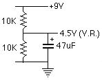
Power Supply - What is V.R., V.B, VREF, 1/2V+ etc....?
Well, V.R. is voltage reference and 1/2V+ is 1/2 of your most positive voltage (usually 9 volts). Usually they are one and the same and you can typically see V.R. connected to a resistor that connects to the input of an op amp as in the Shaka Braddah 3, The Rat and many others. Basically if you see 4.5V or V.R. or 1/2V+ ( all the same), you find all the places on the schematic that reference the label and connect them together. So all of the places that reference V.R. would connect together; one of the connections actually creates V.R. or 1/2V+. The connection that usually creates V.R. or 1/2V+ aka 4.5V (for a 9V battery) usually is a voltage divider. Typically two identical resistors, one to V+ (such as 9V), the other to ground. The place where they connect is V.R. or 1/2V+.
How is VREF calculated?
Again, GEOFEX.COM has a great explanation!
An example of 1/2V+ also known as V.R., V.B., VREF, 1/2V+ etc...
misc - I'm looking at a PCB and I see points A,B,C,Grnd,V+ etc... Where do they connect to???
They are usually places where you put a wire into the board and it connects to a potentiometer or ground wire of the input jack or the plus side of a battery. Look at the schematic for the PCB and these points should be labeled.
Power Supply - I would like to try running my pedals at 18 volts with 2 batteries. How do I get 18 volts out of 2 batteries?
Take 2 battery clips, connect the black (negative) of one to the red (positive) of the other clip. Now use the two remaining clips as usual, when you measure the voltage with a multimeter with fresh batteries, you will measure around 18 volts.
You should verify that your capacitors are rated to handle the higher voltage.
What is series and parallel when connecting two batteries? What is the difference in voltage?
Power Supply - want 18 volts but I want to use one battery.... is this possible?
Yes. Check out this simple Voltage Doubler Circuit. Check out GEO's circuit sweepings! In general, if you can, use 2 batteries - it's easier.
I purchased a wall wart and even though it says 9 volts, when I measure it I get 14 or 16 volts. What's going on?
You have an unregulated power supply. You can turn it into a regulated power supply by using a voltage regulator like the LM317. See this thread.
Power Supply - How can I get a negative voltage out of a single battery for a bipolar power supply?
Check out the ICL7660 7662, LT1026, voltage converters. They can double, produce negative voltages etc... from a single battery.
I've got one of those SKB powered pedalboards. Is it possible to lop the tip off one of the power cords and rewire it with reverse polarity to power a PNP pedal?
From Zachary Vex:
Only if it's the only pedal you are powering with the power supply. if you are also using that same supply normally with other effects, you'll be shorting +to - at the ground connection when you attach one pedal to another...think about it. the plus side is ground on the PNP box, and minus is ground on the others, then you connect the grounds together...fizzle!
the only way to do it is to connect a second supply that allows you to make the negative connection on your PNP pedal BELOW groundlevel. so you can lop off a connector and reverse it to powera positive ground (PNP fuzz face) pedal, but it has to be connected to a different power supply.
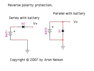
How can I protect my circuit from a backwards battery?
Check out this article from geofex.comon circuit protection and other tricks.
Simple methods: Diode in series or parallel
What is the best way to add a 9V wall wart to my fuzz clone? What can I add in terms of filtering to insure, or at least cut down noise for low noise operation?
From Rob Strand:
The simplest suggestion is to put a 100 ohm resistor in series with the power rail (ie. -rail for PNP, +rail for NPN, not that it really matters) then a 100uF electro across supply, on the effect side.
Phillip Marshall contributed even more ideas!
How do I put jacks for 9V adaptors on my pedals?
JD did all the work here:
Effects Power Switching and Adding a Power Jack.
JACKS
Jacks - Do I use mono or stereo jacks?
Unless you have a special pedal that requires otherwise, use a stereo 1/4" jack for the input of the pedal (so you can unplug your instrument cable to power down the effect) and use a mono jack for output. (See next question for how to wire the input stereo jack). For the output, you use a mono 1/4" jack and the tip lug of the jack is connected to your circuit's output signal and the sleeve lug is connected to ground. The difference between a stereo jack and mono jack is that the stereo jack has 3 lugs (tip, ring and sleeve), while the mono jack only has tip and sleeve.
How do I make the input jack switch the power on and off?
Get a stereo 1/4" jack for the input of your pedal. Connect the tip connector to the input of the effect. Connect the sleeve to the ground of your effect. Connect the 3rd connector (the ring) to the negative of the battery (or the positive if your pedal uses a reversed power supply such as the Tycobrahe Octavia or some Fuzz Faces). When the cord is inserted into the jack, the ring connects to ground completing the circuit.
In other words, plug in your guitar cable to turn on the circuit, unplug it to turn the circuit off and not consume batteries.
In the above picture, do not assume that the lugs shown are connected to the nearest closest connector. In many cases they are not.
In many cases the lug is connected to the connector farthest away from it. For example, the ring lug is on one side of the jack, but the ring connector (the part that touches the plug) is on the other side of the jack. When in doubt, use your multimeter to test continuity.
How do I isolate my jacks from the enclosure?
From R.G.
Two choices: (a) get insulated bushing jacks like the Switchcraft N1xx typesor the ReAn nylon body ones (excellent choice, that). Mouser has both. (b) buy the white nylon bushings that Mouser offers. These fit a 1/2" hole and have a 3/8" hole for a standard jack.They're used a lot in isolating input jacks for tube amp hum reduction.
From JD
If you want to go with the nylon washers, here are the Mouserpart numbers for the washers that work with Switchcraft jacks
561-SW375 - Nylon Shoulder Washer 561-D37562 - Nylon Flat Washer
1/4" Jacks, open-circuit or closed-circuit?
From Steve Daniels/ Small Bear Electronics
- For most pedals, you want an open-circuit stereo jack for the input (Switchcraft #12B), and an open-circuit mono for the output (Switchcraft #11). The "sleeve" contact of the input jack is wired so that the battery is disconnected when the guitar plug is removed. You can see this method of wiring on a number of DIY sites.
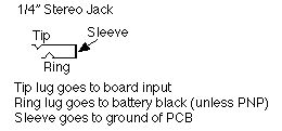
Tip, ring, what lug does what?
Question: All effects circuits have an in and an out.. which lugs do these go on on the jacks?
- The signal of the circuit goes to the tip of the jack. The ground of the circuit goes to the ring of the jack. So the input to the circuit goes to the input jack tip lug and the output of the circuit goes to the output jack tip.The ground of the circuit connects to the sleeve lugs of the jacks.
Does the DPDT/3PDT turn the power on and off? No. If you wire your stereo input jack like described in this FAQ, power is not used when the pedal is unplugged. Power is used whenever the pedal is plugged into the input jack. The DPDT or 3PDT only works on the signall (with the exception of the LED if used) and does not switch the power on and off.
TRUE BYPASS AND SWITCHING
Bypass - What is true bypass and what is a DPDT switch?
Read this excellent article by R.G. Keen on bypass methods.
Also check out my simple Elementary Bypass Article.
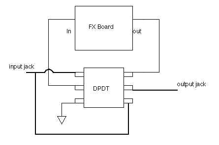
Bypass - How do I wire a DPDT switch?
Check out this picture.
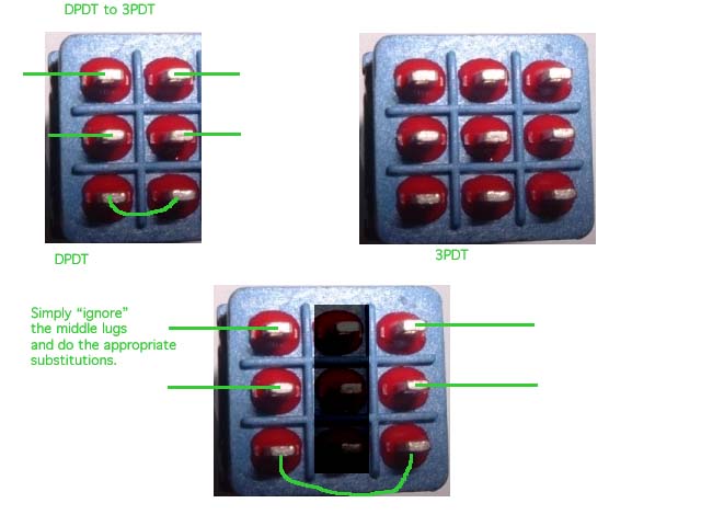
Bypass - I have a DPDT but I want to use a 3PDT instead; there are more lugs on the 3PDT, how do I do this?
Check out how to go from DPDT to 3PDT.
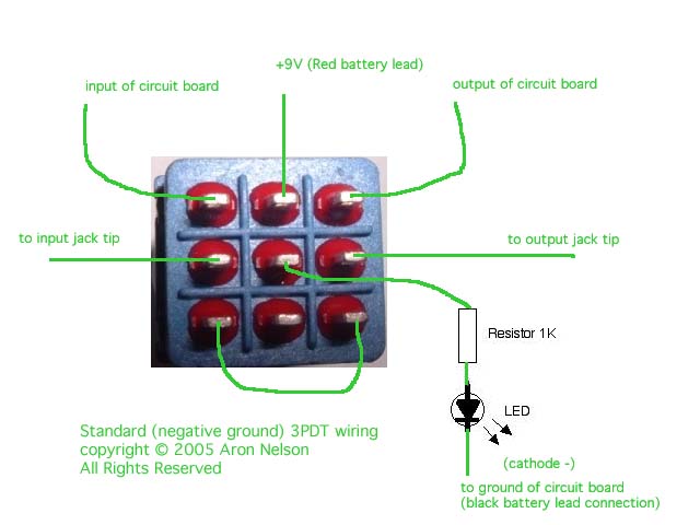
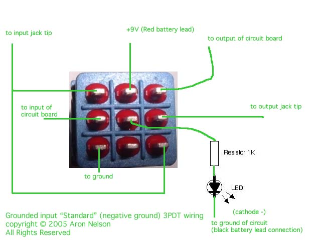
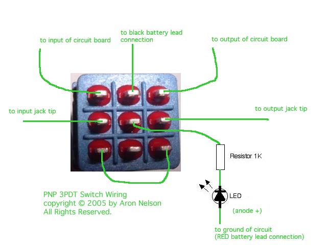
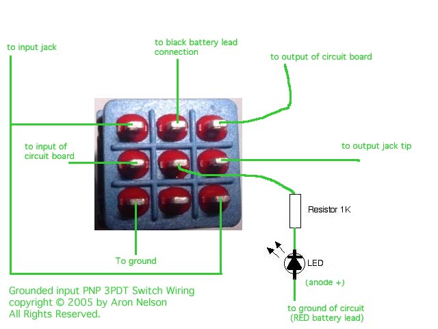
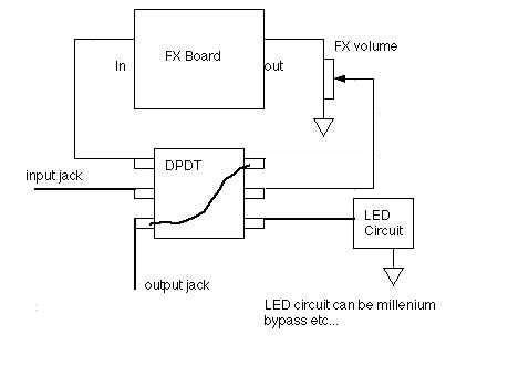
Bypass - How do I wire a 3DPDT switch with LED?
There are several ways depending on whether you have a "standard" negative ground circuit (most circuits are) or a positive ground circuit (like the Fuzz Face or Rangemaster). Positive ground circuits have the RED wire from the battery connected to ground which is opposite from most "standard" guitar pedal circuits.
For the standard circuits: standard wiring and alternate (grounded input wiring) The grounded input wiring is probably better since it grounds the circuit input when in bypass mode.
For positive ground circuits: standard wiring and alternate (grounded input wiring).
If you want to omit the LED, simply ignore the middle set of lug connections and omit the resistor and LED.
Also check out this simple page on bypassing: Elementary Bypass.
Bypass - Where do I purchase a DPDT or 3PDT switch?
Support DIYStompboxes.com by ordering from the store
For DPDT, order from Small Bear Electronics. (Carling 316)
Bypass - What's the deal with the cheaper switches I see available... can I use them?
Yes. You can use any type of DPDT stomp switch, the issue is reliability. As of 7/1/01, there is no better DPDT switch than the tried and true Carling switches. The other "Arrow" copy DPDT switches are fine for home use where you can swap them out anytime if they fail (and most cheaper switches seem to fail). For gig use, I recommend Carlings. I have heard the Fulltone 3PDT switches are good.
NOTE: I now use 3PDT switches because they are much easier to wire for true bypass. I have found them to be reliable as the Carlings I have and much cheaper. I make them available for a reasonable price.
Bypass - I have an Ibanez Tube Screamer and the switch broke, what can I replace it with?
From CJ Landry: The part is made by E-Switch with the part number TL1100 and the Mouser P/N is 612-TL1100. I have been using this part for a long time when replacing the TS-9 style switch. You might want to add a second source. The second source is also a Mouser part made by Mountain Switch. It's Mouser P/N is 101-0621. The difference between these switches is the square top (on the plunger). The size seems to differ between the E-Switch part and this Mountain Switch part. I have not looked at detailed specs for each switch, but would try the switch which has a longer operating life. This is the number of switch actuations it can handle before it fails. They both work fine and I have no personal preference.
Bypass - have any info on relays?
Yep, GEOFEX.COM again, Relays for Switching Audio Signals and Remote relay switching.
DIODES
Diodes are polarized similar to electrolytic capacitors; there's a positive and negative end. The cathode is the negative end of the diode and the anode isthe positive. The main thing for you to remember is that you need to orient the diode correctly with the schematic.
LED is a light-emitting diode.It has a cathode as well and it is usually marked with a flat side or dot or in some cases a groove in the LED. Read more about different LEDs. Sometimes there is a longer and shorter lead. The shorter lead is usually the cathode (negative), longer lead the anode (positive).
Misc - What is Si, Ge??? I see this all the time?
Si = Silicon, Ge = Germanium.
Diodes - Give me a quick rundown on basic diode types....
From Rob Strand:
You need to find at least one of each types too have a look at. Most diodes of the same type look similar in size. The size grows and lead thickness grows with increasing current handling. Most diodes have a band at one end which is the cathode and many have a part number stamped on them. Diodes can look similar but may be completely different!!Here a _quick_ rundown on the key points:Germanium: 0.3V, low currents, fast, usually clear+striped bandsSmall signal silicon: 0.6V, low currents, fast, small glass, often copper coloured. Few variations: blue/green/yellow stripes and no part number, black bands with part number, multiple coloured bands and no part number.Power silicon: 0.6V, high currents, slow, usually black plastic with silveror white band and usually a part number.Power silicon-fast: 0.6V, high currents, fast, look same as Power silicon.Small Signal Schottky: 0.35V, look like small signal silicon and zenersLED: 1.8V, unmistakeable, different colours available.Zener: 0.6V one direction and zener voltage in other direction,look like small signal diodes but are often coloured witha part number stampedSmall diodes without part numbers are very hard to identify exactly but are usually small signal silicons or maybe zeners (if it has a number like 5B or 0A (for 5V, 10V) stamped on it).
How can I change the kind of distortion I have - or make it more fuzzy using diodes?
Read this detailed message from Mark Hammer.
When should I use silicon or germanium diodes?
Read this detailed message on diodes from Mark Hammer.
How do I wire a FET as a diode?
Anything more on diodes?
Doug Hammond pointed out this link: The Unusual Diode FAQ.
What is a low leakage diode and how can I find one?
What is a zener diode?
TRANSISTORS
You will have to work with transistors in some stompboxes. The middle line is the base (B). One of the lines will have an arrow, that's the Emitter (E), and the last line will be the collector (C). If the arrow points away,it's an NPN transistor. If it points in, it's a PNP.
 NPNTransistor
 PNPTransistor
Once you have identified the lines on the schematic, you need to identify the pinouts on the transistor and match them to the schematic. Refer to the diagram that comes with the transistor . Lots of transistors use standard package types. Some transistors have unusual pinouts so always checkthe diagram or obtain a datasheet on the transistor.
 This picture shows the FLAT side up of the transistor. You will often see this picture in pinout diagrams. Sometime they don't tell you this is the flat side...
FETs
For all the circuits that use FETs, I now recommend J201 FETs. At a very low cost, they are reliable and great! The have the same pinout as the MPF102 in a TO92 case.
If you cannot get the J201, I also recommend using NTE458 FETs instead of MPF102. The NTE458is about $1.80 around here.
Here is an example of a FET in a schematic that you might see:
 FET
FET
Note the G (Gate), S (Source)and D (Drain) markings.
Many schematics will omit those markings. Refer to this picture if you get confused.
TRANSISTORPACKAGING (Cases)
A common thing is for transistorsto use a specific package type.
Here are some common pinouts for some standard package types. Note that there are variations in pinouts and variations of T092 etc... Check your datasheet, which describes the pinout of your component.
I can't find a xxxxx transistor! Where do I find a replacement/substitute???
Try this: go to [www.nteinc.com www.nteinc.com],click on Semiconductor (for searching) and type in the transistor number.If there is a replacement made by NTE, it will be shown and you can look at the data sheet if it's online. Since NTE and ECG share the same numbers, you should be able to find either NTE or ECGparts at your local electronics store. Usually these replacements will work fine. Only in very special circumstances will the replacement parts fail to work.
Here's a thread on replacement transistors for NPN and PNP transistors and FETs.
How do I find out the pin out of a transistor or op amp?
For the most part, go to [www.nteinc.com www.nteinc.com],click on Semiconductor (for searching) and type in the transistor number.If there is a replacement made by NTE, it will be shown and you can look at the data sheet if it's online. On the bottom of the page will be a picture of the pin out. IN MOST CASES, the pin out will be exactly the same as the original part. If it's different,the NTE web site will note that the pin out is different.
Since NTE and ECG share the same numbers, you should be able to find either NTE or ECG parts at your local electronics store.
Also check out these datasheets:
http://www.mouser.com/index.cfm?handler=supplierpage Mouser's Links to companies.]
Also check out:
http://www.repairfaq.org/sam/semitest.htm Basic Testing of Semiconductors]
Here's another link to an information resouce on transistors
http://www.americanmicrosemi.com/products/specs/Transistors.phtml
Misc - What is germanium? Where do I find germanium transistors and diodes?
Germanium is a metallic semiconductor and early transistors and diodes were made from it. You can read about the history of the transistor here. Some early circuits like the Fuzz Face and Tone Benders used germanium transistors. You can find germanium transistors from NTE as well as other electronic places. Small Bear Electronics and my store offers matched transistors for building these circuits. The typically used germanium diode, the 1N34A is available from my store.
Transistors - Can I just stick a germanium transistor instead of silicon in a circuit?
In general, no. You need to rebias the circuit for the germanium transistor.
What's up with this "matching" transistors for Fuzz face type circuits? Do I have to do this?
No, you don't have to match them, but the circuit may not sound as good. It has been noted that matching transistors in the Fuzz Face could give you that elusive sound that the highly sought after Fuzz Faces had. GEO has a great article that explains this and most boutique pedals carefully match their transistors by hand. Small Bear has a great article as well! You can do this too. Just buy a ton of transistors and measure each one until you hit the "magical" points on a couple of transistors. Of course this could cost $$$. For a great alternative, utilize the services of Small Bear.
You can also simple rebias your Fuzz Face by altering the bias resistors.
Where can I find germanium transistors for Fuzz Face circuits?
How about buying some matched transistors for a really great price!? Go to Small Bear Electronics and order a pair.
- Courtesy of Jack Orman:
- Since the supply of 2N388A transistors have been depleted at Parts Express, I thought I'd post a few alternate devices
- that they carry that can be used for F-F construction. Any of the below parts should be suitable and are less than $1
- each. The last one is spec-ed a little weak but would likely be okay. The first one is a good sub for the 2N388A.
- Part No. Type Hfe Price
- 2N1306 NPN 100 $ .95
- 2N1308 NPN 150 $ .75
- 2N1309 PNP 150 $ .75
- 2N1373 PNP 60 $ .95
- The NTE101 is another choice:
- http://www.nteinc.com/specs/100to199/NTE101.html
- I've heard that the NTE158 might be another choice:
- http://www.nteinc.com/specs/100to199/NTE158.html
Darn it! I just bought a TON of NPN Germanium transistors... I thought they were PNP. Can I use them?
Hah! This happened to me. Well, it's pretty darn easy to convert PNP circuits to NPN. Reverse the polarity of the Electrolytic capacitors, diodes and the power supply. It worked fine for my Fuzz face and Tone Bender.... Very nice! (Note, this doesn't work for every circuit, particularly high-gain circuits, but it's worth a try) For PNP to NPN do the same. Reverse the orientation of all electrolytic capacitors, diodes and power supply.
Why does my pedal have a horrid crackling or "gating" sound when I play? I have to hit the strings really hard to get it to make sound and it's horrible.....
You have a classic case of a mis-biased transistor(s). Check out the Debugging page, especially the section on bias problems.
What about biasing a silicon transistor?
Check out this page.
Also check out the EMF for a great calculator to use when biasing a transistor.
How can I find out more about transistor biasing?
From R.G.Keen:
By far the most comprehensive and comprehensible book on transistor bias and gain that I've run into is "Practical Transistor Circuit Design and Analysis"by Gerald Williams; 1973 McGraw Hill, TK7871.9.W53, ISBN 0-07-070398-1.
What about buffers?
What is the pinout of the 2N5088/2N5089?
E B C, flat side up, left to right.
I see 2N5088 all the time but it's NPN, what's a PNP substitute for the 2N5088?
From R.G.Keen:
Use a 2N4250. 4250 is not exactly a complement of the 5088, but it's pretty good for any silicon PNP uses.
The 2N5087 is also the PNP complement of the 2N5089.
What is the pinout of the 2N5087?
E B C, flat side up, left to right.
What's a generic replacement for NPN and PNP transistors?
From R.G.Keen: When in doubt, use a 2N5088 for NPN's and a 2N4250 for PNP's. You can purchase NPN and PNP transistors from the store.
What's a replacement for the 2N5088?
From R.G.Keen:
2N5089 will work in most instances. Also useful are 2N5210, 2N4401, BC549.
What FETs can I substitute in the Mini-Booster and Shaka etc...? I can't find the J201....
From Jack Orman:
This is a recurring question eventhough the information was in the Mini-Booster article at AMZ From the article: "The NTE458 usually has more gain than the J201, and the 2N3686 can provide gain of 500. The 2N5457, MPF102, and 2N3819 will produce less gain. Other substitute transistors include 2N5484, 2SK43, 2SK68, 2SK117, 2SK118, 2SK121, 2SK163 and BF245."
What is the pinout of the J201?
It's the same as the MPF102 (see pinout diagram at the bottom of this page). Flat side up, legs pointing down, DSG from left to right.
Is there a general spec that tells me if a FET has more gain or not?
From Jack Orman
"FETs with a low V pinchoff usually have high gain. The Yfs (or Gfs) spec is a general indicator of gain as well... Yfs of 1000 is low gain, 3000 is moderate and 12000 is smokin'" (Thanks to Jack Orman for this tidbit!)
Where can I get a simple explanation about biasing a FET as an amplifier?
Read about a FET amplifier here at Graham Knott's page. (Thanks Mike B.)
Here's a great thread re: FET biasing
FET biasing calculations thread
What is the pinout of the BS170?
Flat side up, left to right: D G S. Note that the 2N7000 that is a substitute for the BS170 has a different pinout. The 2N7000 is S G D flat side up, left to right and usually requires a different value bias resistor from the BS170.
I see that a lot of pedals you use have FETs, what other types of FETs can I use since I can't find many of them?
Here are some FETs that you can try:
2N5457, 2N5484, NTE458 , ECG458,or J201. The J201 can be found at www.techamerica.com and Future(1800-655-0006). The NTE and ECG FETs should be at most major electronic stores. The 2N series can be found at www.mouser.comas well as all the other places I list.
Here's a cool link re: FETS (PDF)
What's a good meter I can purchase?
Check out this thread for some suggestions.
How do I measure transistor gain?
The easiest way is to get a multimeter that can measure transistor gain (hFE). The cheapest one I have found is from Hosfelt: 9202- Multimeter, just $12.95.
What is hFE?
RESISTORS
1/2 vs 1/4 watt resistors which ones???
For most if not all of our stompbox effects, 1/4 watt resistors are used. You can use 1/2 watt resistors but they take up more space and do not provide any benefits. Yes, you can mix and match 1/2 and 1/4 watt resistors in a circuit.
What does 4K7 and 1K2 mean for resistors?
"That is just the European notation. They replace the decimal point with the multiplier letter.This prevents the possible loss of the decimal point in transcribing data. For instance, 4.7K = 4K7, 1.2K = 1K2, 1M = 1M and so on.
You'll also find the Euro use of "nanofarads", meaning 1/1000 microfarad or 1000 picofarads.For example, 0.001uF = 1nF = 1000pF. 0.022uF = 22nF.
It's handy, and less error prone." (Thanks to R.G. Keen for this reply in the DIY forum!)
I don't have xxK resistor!
You can put two or more resistors in series and their values will add up. The EMH has a calculator for this.
I recently read somewhere that using carbon composition resistors in an effect circuit would help to create "brown sound". Are carbon comp. resistors really better to use for audio circuits?
Here's a nice article written by R.G.on carbon comp. resistors. Here's another thread on resistors
Is there a visual calculator I can use to figure out my resistor values? Yep, check out the EMF
OP AMP
I need to find that JRC4558 chip that's in the TS-808, I heard you can get them from old radios and other voodoo sources!
Yes, you probably can. Or, you can buy the current chip that sounds the same as the original- so close you can't tell the difference... from MOUSER.The part number is:513-NJM4558D.
What do all the letters after the numbers mean at the end of an IC?
From Rob Strand:
General letter usage (not justTLO7x, and all options may not be available):
The A and B refers to offset voltage categories. Non-A/B versionshave the highest, then A, then B.
The C, I, M referes to the temperature range, widening/increasingin that order.
The P, N, H, J refers to the package type/material. Usually D means a surface-mount package.
Sometimes the different package material implies different operating temperature ranges.
Basically you are safe with any of these except D. For Audio projects usually the cheapest is OK. Using low offsets, wider temp rangeand different packages _usually_ means you pay more, and if you don't need the options you're wasting your money.
GENERAL OP AMP INFO
If the circuit uses an IC (usuallyan op amp), then you will see something like this in the schematic:
 IC in schematic
In this case, you need to lookup the datasheet for the op amp. Note that you can use a TL071 and have a great low noise substitute for a 741 chip.
In this case, lets pretend it was a TL072 op amp. Here's the pinout for dual op amps such as the TL072, JRC4558:
 Dual Op Amps have this pinout (TL072, JRC4558).
Referring to the IC in schematic picture above, the wire going into the minus sign is the InvertedInput/pin 2. The wire going into the plus (+) sign is the Non-InvertedInput/pin 3. Vcc refers to the Vcc (+) input /pin 8. The groundgoes to Vcc(-)/pin 4. The wire exiting the IC in schematic is the Output /pin 1. Since the TL072 is a dual op amp, there are two sets of Input and Outputs. Sometimes circuits will use both amps (inputs and outputs), sometimes it will use only one set. In both cases, Vcc(+) and Vcc(-) will have to be connected. Vcc(+)goes to positive power. Vcc(-) goes to ground. If only one of the op amps are used, the other set of inputs and outputs can be left disconnected. In some schematics, the Vcc(+) (power) and Vcc(-) ground will not be shown. This does not mean you don'thave to connect these pins, you have to; the schematic writer is assuming you already know this..
Let's look at a typical circuit using a popular chip, the LM741. This chip was used in the MXR Distortion+, Dod Overdrive and many others. Although widely used,it's a noisy chip. You can replace the chip with another lower noise op amp like the TL072 if you are building your own circuit. Note if you are modding an existing pedal, use the TL071 - a direct chip replacement.
 example circuit using 741 chip
 <-LM741 Chip pinout
See how the -(minus) sign is the Inverted Input? See the power V(+) on pin 7 and the ground which is pin 4 V(-). To use a TL072 or equivalent, you need to map the LM741 pinouts to the TL072.
TL072
LM741
To use a TL072 instead of an LM741:
The connections that connect to Output pin 6 of the 741 connect to pin 1 on the TL072
The connections that connect to V(+) pin 7 of the 741 connect pin 8 of the TL072
The rest of the connections are the same.
Always use IC sockets on yourboard. That way, you don't expose the IC to heat when soldering and you can always substitute a different IC later. For example you can try an RC4558 or TL082 etc...
Here's a link to some op-amp basics. Here's a link to a thread re: op amps
Here's a TI article (PDF) Called Op amps for everyone by Ron Mancini Good Read!
a thread about VREF and bias currents of opamps.
WIRE
What kind of shielded wire should I use?
If you can get it, single conductor with shield - RG-174 Belden wire. Very good and it's flexible too.
What kind of wire should I use in my pedals?
In general any type of hookup wire will work - from size 22 gauge and smaller. (The larger the number, the smaller the wire - so 26 gauge is skinnier than 22).I like the "pre-bondedhookup wire" from Small Bear Electronics. It's a cross between stranded and solid core - very nice. In general solid core will stay where you want, but will not like being moved and can break easily. Stranded is much tougher but resists bends and will generally not look as "neat" in an enclosure. Ifthe circuit is being mounted in an enclosure and will not be removed- solid core is ok. If the it's going to be moved at all, I recommend stranded wire or the hookup wire mentioned above from SmallBear.
ORDERING
I live in another country, what's a good place to order from?
Try FutureElectronics - a global company with lots of transistors!
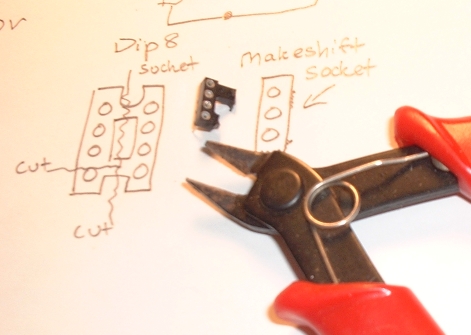
Where do you buy your transistor sockets from?
If you must purchase, I buy these: Mouser part: 151-TO-1832OG. 151-TO-4320G and 151-TO-18320G. Most 3 pin sockets will work fine. Most times, I simply cut up an 8pin DIP now.
Also see Small Bear Electronics.
Where can I get a printed circuit board (PCB) layouts or ready-to-solder board (RTS) for effects?
Check out GeneralGuitarGadgets.com
ENCLOSURES
Where do I find the boxes to put this stuff in?
Commonly called "enclosures"in your favorite catalog, they are made by Bud, Hammond, LMB etc...Aluminum boxes are easy to work with compared to steel. If you want a solution that's cheap but a little harder to work with,check out electrical outlet junction boxes. Thanks to Jack Orman for the tip.
I have been using the 1590BB Hammond box that R.G. recommends. It is so great to build into a box that is sturdy, has enough room and looks good. SmallBear Electronics is now offering the 1590BB for a very good price!. For a smaller box, check out these aluminum enclosures.
MEASUREMENTS
How can I measure how much current my pedal is drawing?
To measure the current draw of your pedal, you put your meter in series with the power supply and measure the amperage.
From F Peña:
You have to interrupt the circuit measure current.
Do this:
Set your DMM on DC/mA.
Plug only the - side of the battery to the battery snap.
On the + contact of the battery, touch the red probe and on the free
contact of the battery snap touch the black one.
You should get the reading on the meter this way.
How do I measure voltages in a circuit?
Set your meter for DC, put the black probe on a ground point and probe using the red probe. Read the DC measurement on the meter.
How do I measure inductance?
You need a meter that can measure inductance. Here's one.
Testing - I'm testing out a pedal I made and I want to test it out with a function generator. What kind of signal should I use?
From Zachary Vex. Put the output of the function generator on a scope, set it for around 400 Hz, sine wave output, 100 mV peak-to-peak, and use a 47k resistor in series between it and the input to your pedal. you can increase the output to as much as 1 V peak-to-peak safely, i think, and you should monitor the output of the generator on a meter or with one trace on the scope while you monitor the output of the circuit with the other trace, if it's a dual-trace unit.
Are there other tests I can do with just a multimeter?
Yep, check out: Basic Testing of Semiconductor Devices.
Can I test a capacitor with my continuity function?
You cannot test a cap with the continuity feature. The continuity feature of most meters will only beep when there is very low resistance.
See this link for more details:
again, thanks to R.G. for finding this great link.
Impedance ... more in it
Asked a while ago in the forum
How to measure input impedance
in this thread from the forum.
COMMON WORDS AND TERMS
See this section of the Wiki for a list of commonly used terms:
Terms - What is PCB and RTS???
Printed Circuit Board and Ready to Solder when related to stompbox electronic projects.
For example:
CALCULATIONS/FORMULAS
Check out the Electronics Math Helper. VERY COOL!
Check out Marcelo's Bias Calculators
What is the formula for calculating the knee of a RC (resistor/capacitor) circuit?
This can also be used to calculate the rolloff of an emitter resistor/capactor.
From R.G.Keen:
A resistor and capacitor are halfway to whatever they will do - highpass or lowpass - when the capacitive reactance equals the resistor. That is, when Xc = 1/(2*pi*Frequency)=R, the filter is at its knee. So with a little elementary algebra,Freq. = 1/(2*pi*R*C).
The units are ohms, hertz andfarads.
For the TS series feedback loop(for example), this comes out to (1/F)= 2 * pi * (.000000047Farad) * (4700 ohms) = .001387 Sec
F = 720.8Hz.
You can play games with the decimal points. If you use C in uF and R in megohms, you get
F = 1/(2*pi*.047uf*.004700M) =720.8Hz
But I prefer not to mess with remembering special cases of uF/Mohm, etc. Just do it in farads and ohms and keep the decimal point straight.
For emitter bypass capacitors:
From niftydog:
There are three factors that might determine the ƒ rolloff. The input cap, the output cap and the emitter bypass cap. The -3dB point is determined by the "worst" of these formulas.
For ƒlow due to Cin, you need to know the signal source impedance and the input imedance of the amplifier itself. Not a trivial excercise, so I won't go down that path, unless you really want me to!
For ƒlow due to Cout;
ƒlow >= 1 / [2pi.Co(RC +RL)]
Co = output cap, RC = collector resistor, RL = load resistor.
For ƒlow due to CE;
ƒlow >= 1 / [2pi.CE(re +RE1)]
CE = emitter cap, RE1 = non-bypassed emitter resistance.
re is the dynamic resistance of the emitter and can be approximated by;
re = 30mV / IE (±40%)
from Transmogrifox:
Here's the summary that has relevant information that will get you into the ballpark:
f3dB ~ 1/ (2*pi*R*C)
and R is most significantly defined by the emitter output resistance, so ignore the rest of the effects and just calculate R as
R ~ Re ~ Ic/Vt = (Collector Bias Current) / (.025) at room temperature.
How to predict battery life
DEBUGGING
See the Debugging page in the Wiki
How do I debug and fix my effects?
Check out GEO's FX Debugging page and mine.
I am getting a whine - like feedback but high pitched when I turn the drive all the way up...how can I fix this?
You probably are running the leads of the input and output too close or they are too long. Keep the leads as short as possible when laying out your box. You may also want to consider using shielded wire. To do this, shield the wire on one side only and then connect the single conductor like usual. For high gain boxes, I recommend shielding the input and outputwires from the jack to the switch and from the switch to the board.
You can also try using a 3DPT switch and using the outer connections for signal switching and use the "inner" connections for LED switching.
Fixing Power Fried Pedals
Check out the thread on this. Great reply from R.G.
POPS
Pops when switching, even with pulldown resistors
From R.G. Keen
- There is a weak link in the power/ground setup in most effects using stereo jack switching. You can get pops when switching the relatively high LED current even if you have pulldown resistors on both input and output caps.
- The culprit is ground noise. The ground noise happens when the sudden start and/or stop of current in the LED makes the signal ground voltage change suddenly. +9V decoupling may not help, and may make it worse.
- The ground noise comes from our friend, the stereo jack ground switch. If your jack is new and the plug is new, things work great. When dirt, oil, crud, bar funk, and other nasties build up on the ground ring of the input jack and the second-channel contact that supplies ground through the plug into the input ground ring, and thence to the effect board, the resistance through that path can get high enough to make a noticeable pop when the LED current starts and stops.
- This sudden transient is worse with mechanical switches because they really do go from fully off to milliohms of resistance in zero time when the metals contact. The sudden "ground bounce" can flow right into the input of your effect, and it doesn't take much to hear a pop from the input of a gain-of-a-zillion MegaBlaster.
Also another thread on popping. [See the post by R.G. http://www.diystompboxes.com/smfforum/index.php?topic=68210.0]
What to do, what to do??
- (1) Clean your plugs and jacks. Yep, and do it again. And again, every so often.(2) Use the OUTPUT jack for power switching - it's less sensitive by the gain of the pedal.
- (3) Use the GEO scheme for cold-switching +9V by using a PNP transistor with it's base tied through a resistor to the stereo lug on the input or output jack, and the battery minus tied directly to the board. The PNP transistor only lets +9 through when its base is pulled down by the plug in the jack, but this current does not change noticeably when the LED is started, and so any ground bounce is only through the hard-soldered milliohms of the battery lead, and is much, much smaller.
- See the power supply switch in the Neutron filter at GEO or at GGG, or see the positive 9V switch in [1] for how to hook up the PNP.
![[1]](http://geofex.com/FX_images/oaspltr.gif)
Measure for DC
PEDAL SPECIFIC
Negative Ground with PNP Fuzz circuit????
Here's a WARNING about converting a positive ground circuit to negative ground. (as in a Fuzz Face)
My LPB-1 cuts highs off of my guitar. Anything I can do?
From: Matt Farrow
Pharaoh Amplifiers
There are a few things that you can do to increase the treble response.
- 1. Switch to a different device. Any bipolar transistor will have a characteristic high-frequency response and gain. Usually the higher the gain of the transistor the more high frequencies it can amplify. Try a 2N5088 or 2N5089 for a start. 2N2222 can work but will be duller-sounding.
- 2. Increase the input impedance of the circuit. You can do this by changing the biasing resistors on the base of the transistor, keep the same ratio (on an LPB-1/2 it's usually 10 to 1, 470K to 47K - try 1M and 100K) and also by inserting a resistor in series with the base (after the input cap works better but try it both ways.)
- 3. Decrease the input cap to block low freqs. The stock .1 is too much for my ears unless you're using it for bass. Try a .047 or a .033.
Any tips for a Big Muff modder?
Check out this post from JCM: JCM on Big Muff mods.
I want to mod my wah, any information on this?
This thread is very informative re: inductance
I finished building a Foxx Tone Machine (FTM) and it sounds great but I am having problems figuring out how the full wave rectification happens in the circuit. I have scoured my electronic books for some clue but to no avail.
From R.G. Keen:
- Consider transformer rectification. A center tapped transformer as in the Octavia makes two versions, one following the input signal and one inverted in polarity from the incoming signal. The diodes allow only the currently-positive version to appear at the output by each letting signal through only when the signal feeding it is positive. This happens on alternate half cycles, so you get full wave rectification.
- In the FTM, the out-of-phase signals are generated in a transistor phase splitter - the transistor with equal collector and emitter resistors. The two diodes are biased slightly on by the resistors around them so that the effect of the diode forward voltage is largely canceled out. But each diode merely conducts when its anode is more positive than its cathode, just as in the transformer case. The diodes think it's the same thing.
How can I increase the "slope" of my filter and get rid of the fizziness?
- note* taken from a thread re: the Rat tone control...
From Mark Hammer:
- The "Filter" control on the Rat is, as noted, a single-pole adjustable lowpass filter that will roll off highs by 6db/octave starting from around 475hz (when the pot is at maximum resistance of 100k) and tunable up to 32khz (when the pot is set to minimum resisatance and the filter is determined by the cap and 1.5k fixed resistor). Some folks, myself included, find the upper range of the filter to be relatively useless, and so have changed the filter cap from .0033 to .0047 (or larger). With a .0047uf cap, the tuning range shifts to 334hz-22.6khz, which is a bit better.
- But lets look at the bigger picture...
- The purpose of such hi-cut filters is to take out the fizziness and impart some warmness. Because the filters have such a shallow slope (only 6db additional rolloff for every octave higher), you have to set your rolloff frequency quite low to have any chance of attenuating much higher frequencies to the degree you'd like.
- Think of it like an aircraft carrier. How long would it have to be to accommodate aircraft that needed a long running start to attain liftoff? Fortunately we can shorten the "liftoff time" by opting for a slightly more complex filter without drastically complicating or impairing the circuit.
- If one uses a dual-ganged pot as the tone control, it becomes possible to create a steeper filtering action by having 2 poles (12db/octave rolloff), so that you can have double the reduction in high-end fizziness without having to remove too much of the "body" of the sound. Moreover, the opportunity to cut high end more sharply means you don't really need as much tuning range to achieve a noticeable variation in tone.
- The Rat circuit assumes a total series resistance range of 1.5 to 101.5k. We could duplicate that but as noted, we probably won't need that wide a range. I'm going to shoot for a tunable range of 3.3k minimum resistance for each filter section, to a maximum of 53.3k. In tandem with a .0033uf cap for each section, this gives a 12db/octave filter that can be tuned from a rolloff point of around 900hz to around 14.6khz. If you like it slightly darker, change the 3.3k resistor to 4.7k and your sweep range will be from 880hz to 10.3khz.
- A dual 50k pot is pobably ideal, but lets assume they're a little harder to obtain and work with a dual 100k pot (even RS sells them!). The two pot halves are wired up identically as variable resistors (rheostat) in series with each other, so that at one extreme their combined series resistance adds up to 200k or thereabouts (and obviously 0 ohms at the other extreme). You want their combined resistance to max at 100k, so put a 100k resistor in parallel with each pot half to achieve 50k per pot section. The series resistor doesn't really care which side of the pot it goes on as long as turning the pot produces the same type of resistance change for each section. So, one fixed resistor can go on the input to pot half A and the other on the output to pot half B.
- Instead of a single cap from series resistor to ground as shown in the schematic, put a second .0033uf cap to ground at the junction between the two series resistances (keeping in mind the location of your fixed series resistors).
- This change should produce no decline in max output level (maye even a slight increase since you don't have to kill all the midrange to eliminate the hi-end rasp), although whether a dual-ganged pot will fit in your current chassis is another matter.
What's the deal with the limited drive range on an MXR distortion+ clone I made?
Check out this thread regarding the distortion control.
TOOLS
Tools - What's a cool drill bit to buy to drill these metal boxes?
Try a Varibit (possibly called a UniBit as well?). These are stepped drill bits that cover pretty much all the holes you need to drill. I bought the smallest size bit (1/2" max) and it worked for everything up to footswitches. About $20 in my local store.
Typical mounting hole sizes
From (C.Garcia)
For the stomp switch 1/2" is OK and for the jacks it depends on the style:
For switchcraft types is 3/8" to 7/16" (other brands may be a little more or a little less, but within the range)
For plastic types (Marshall style) is 7/16" to 1/2"
What's a low-cost soldering iron I can get
This one is very low cost with replaceable tips.
For a little more, you can get the Weller WP-25 iron and get different tips.
What's a low-cost soldering station I can get?
This Weller WLC100 station is easy to use and works great.
Here's another that the forum members like (AUTO-TEMP 379).
How do I measure inductance?
You need a meter that can measure inductance. Here's one.
MISC
What matters, what doesn't
Here's a link to a thread from our forumers that explains what matters to them and what doesn't when starting out. (Complete with colorful posts!)
What matters, what doesn't....
How to use a breadboard
Check out this thread from the forum
What is series, what is parallel?
How do I connect components in series or parallel?
Series is one component after another. Parallel is when both components are connected so that the components are next to each other with the same leads connected to each other.
How do I put 2 components where there is one presently? I heard that I can put 2 diodes instead of one on my board and it will sound better? How do I fit 2 diodes or components where there was only one?
There are a few ways, but here are a couple.
The first way is if you have vertical space. The second method is if you need to fit the diodes into a tight space.
 Yes, the diodes are soldered in the "middle".
Bypass - I get oscillation/squealing from my distortion when it's bypassed. How do I stop this?
Your pedal has such high gain, that the input needs to be grounded when the effect is bypassed. Jack Orman's alternate wiring method does this. If you need an LED+input grounding, use R.G. Keen's Millenium 2 bypass with extensions.
misc - I am picking up radio stations, how can I stop this?
From Eric Hensel: A 47pf cap to,ground, after the input cap will probably do it --you can adjust this up or down --higher values will start to cut treble. use the lowest value that works.
From Zachary Vex:
Mount the pc board as close as you can physically to the metal box. this will serve as a ground plane to reduce the heterodyning that can pick up rf. don't let the input and output wires cross... make sure the layout doesn't allow input and output connections to get too close to each other. if you can, solder in ground connections around (near) the sensitive input circuitry. if rf is being picked up by rectification, these fixes won't help, but if it is being picked up due to beat frequencies generated by heterodyning (internal rf oscillation in the circuit beating against rf from radio stations) you can get rid of it through the use of careful layout and grounding to reduce oscillation.
You might try using miniature shielded cable inside of the enclosure for the input to the board too.
Bypass - I get a pop when switching my effect in and out. How do I stop this?
The typical method is to put a "pulldown resistor" from signal to ground at the front and end of your circuit. This is implemented as a 1 meg resistor from signal to ground. Just put one at the beginning of your circuit board (before the input cap or start of circuit if no input cap) and another at the end (after the output cap or end of circuit). Look at the many GEO layouts if you need to see a layout using these resistors. If you are not using high quality switches, it could also be the switch.
Bypass - How do I make an LED that shows if my effect is on? Can I do it using a DPDT?
Yes! Check out the GEO Millenium Bypass. I have used the Millenium Bypass with bothMPF102 and J201 FETs. The J201 worked well with the white blinking LEDs I got from Radio Shack. The MPF102 worked ok with the Red LEDs I used. Look at the very clear diagram that Jack Orman wrote for hooking up the circuits. If you make the Millenium Bypass, the wire labeled To Switch connects to the DPDT switch. The +9Vdc connects to the plus terminal of the battery or any +9V connection on the board. The Ground wire goes to any ground on the board or the ground on the jack. The rest of the DPDT is hooked up like the diagram that Jack Orman wrote up.
Bypass - How do I figure out what value resistor to use with my particular LED? If you know the specifics of your LED, use the following calculators to figure it out. Otherwise, start with a 1.5K resistor and increase the value to make the LED dimmer or decrease the value to make it brighter.
Muzique.com LED Calculator (Thanks Jack!)
LED Series Resistor calculator (Bill Bowden)
Misc - What is a breadboard/proto board? Can I test circuits on this?
Yes! A breadboard/proto board is a board with holes that are connected in preset ways. For instance rows of holes will be connected (i.e. wired) together and all you do is stick components into the holes. So to connect a resistor to a capacitor, all you do is stick the resistor lead into a hole, then the capacitor lead into another hole that is "wired" to the first.It's relatively easy to test circuits on a proto board because you can easily substitute different components. The drawback is that the proto board layout can end up not even remotely resembling the layout of the perf board or PCB.
Do JFET circuits need a DC blocking capacitor? I see some that don't have them.
From R.G.:
Most JFET amps, like most triode and pentode amps don't need an input blocking cap under most conditions.
This is because the correct bias voltage for most of these circuits is with the gate (or grid) at zero volts and the source (or cathode)a few volts higher. JFETs, triodes, and tubes are -depletion-devices which means that if you do nothing to them, they conduct like mad. Bias for all of these devices involves holding the gate/grid-lower- than the source/cathode to turn them partially off. Thisis most often done by holding the gate/grid at zero volts and placing a resistor between the source/cathode and ground.
At turn on, the gate/grid and source/cathode are both at zero volts, so the current increases through the drain/plate. This same current has to flow through the source/cathode resistor,so it pulls the source/cathode up above ground, reverse biasing the gate/grid a little. Eventually the source/cathode rises enough that the voltage between it and the gate/grid is just right to keep that amount of current flowing and so it stabilizes at that current. It's so-called self biased.
This is different from bipolar transistors and enhancement mode MOSFETs. These devices are normally off, and you have to do something to the control electrode to make them turn on a bit.
In any case, the correct voltage for many JFET and tube circuits is zero volts DC on the gate/grid, and that just happens to be the only voltage that doesn't need a coupling cap.
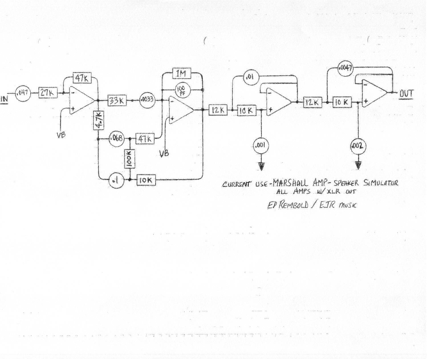
I wish I could make a cabinet simulator; that way I could record direct and play through my boom box etc...
You can. Check out the Marshall type cabinet simulator. This does not replace a miked amp,but is usable and sounds good when going direct.
How do I cut fiberglass PCB boards?
From Paul Perry:
I had to do this for a coulple of dozen boards.. Found the best way was to get a 'tile scriber'which is just a knife sized handle with a tungsten carbide point stuck on. You just clamp the board with a metal edge on it &scrape away heavily a few times, then snap on the scoreline. OK it's trivial & obvious maybe, but I tried to cut them in a bandsaw, DONT even think about it, also fibreglass powder is BAD for your lungs.
I would like to try and write out a schematic of my effect. How do I do this?
What's an easy-to-use PCB program?
I have heard Easytrax is everything we need for making PCBs.
What can I use to view/create PDF files?
You can write PDF files with Ghostscript for free.
What about layout software?
Check out the DIY Layout Creator Software
Where can I check out patents? I would like to see what others have done before....
Try these:
http://gb.espacenet.com/ http://fi.espacenet.com/ http://www.uspto.gov/patft/
How can I make my own knobs?
From R.G. Keen:
Easiest is to cast them from casting resin or sculpt them from Bondo auto body putty or Sculpy plastic clay. Find some plastic knobs you don't like, and break the plastica way from the brass insert inside the knob to get the insert with its threaded setscrew.
For the bondo version, make a filler plug of parafin wax to keep the hole to the threaded hole free and insert it into the set screw hole. Wouldn't hurt to stuff the shaft hole full, either.
Then mix up the body putty, and start building up the knob body. As the stuff cures, it goes through a "cheesy" phase where it's really easy to cut and shape. Once it fully cures, it is hard and solid, can be sanded to avery smooth surface or sculpted by a Dremel with a burr on it.Then paint.
For the Sculpy (FIMA is anothertrade name) just sculpt the stuff on the insert like modelling clay, and bake it according to the directions when you get it right. Not as durable as Bondo, but easier to work.
If the design is fairly simple,make a wax model of the knob, pour plaster over it to make a mold,and then melt out the wax. Pour in catalyzed casting resin until the level just supports the insert, let it harden a bit to hold the insert in place, then do another pour to complete the knob.As with the bondo, use parafin to keep the setscrew hole and shaft hole free of the casting material and melt it out later.
Other people must have asked a ton of questions about all sorts of stuff before right???
Yes! Look at this FAQ archive!!! from Harmony Central!
How can I make a Triangle Knob Big Muff? Where's the schematic? Where's the schematic for a 70's Big Muff.
From R.G. Keen:
To the best of my knowledge, there is no one schematic you can point to as *the* Triangle Knob Big Muff schematic. EH freely substituted parts and values in all its pedals. Stories from original buyers of various versions of the BMP and other EH pedals indicate that the sound quality varied from unit to unit a lot even for the "same" model.
There are 2 versions of traced circuits from real Triangle Knob Big Muffs. As R.G. said, they are both different.
What's up with the swell circuit on the Foxx Tone Machine PCB?
From R.G. Keen: I should have saved my comments on this when I originally posted them. The "swell" circuit on the Prescription Electronics pedal is exactly the same circuit as a 1968(about) article in Popular Electronics by Anthony Leo about building an entire distortion circuit, but it's modestly mis-used to take the output at a place that has a DC level that starts high and drops to about zero over a bit of time. It's also DC coupled out, so the DC level is transferred to the input of the amp that you plug it into. This DC level pushes the input bias of amps that are DC coupled at the input into not carrying signal. Since it's a one-size-fits-all kind of thing, it only works right for amps which have
- (a) DC input coupling
- (b) about a 2V range before being pushed into saturation or cutoff on the input
- (c) NO DC coupling to the speakers!!! Do this on a solid state DC coupled and and you'll fry a speaker. Many tube amps have no input coupling cap, about a 2V range, and are AC coupled, so they work OK. SOME solid state amps are close enough, and can work OK. Some don't work well at all. Oh, yeah. The "swell" circuit only works right when you have very fresh batteries. Older batteries don't make the happy-accident level changing work right. When it works, the volume on each note starts quiet and ramps up to full level, kind of an attack delay. The Experience Pedal is just the Foxx Tone Machine circuit followed by the A. Leo Fuzz circuit, and some very, very complex switching.
I have an old 3 knob memory man delay, NOT STEREO. I play it and it passes signal when on and off but no effect. Do you guys think it is the rare mn3005 delay/chorus IC gone bad???
From Mark Hammer
The chip may actually be okay, but you may need to do an adjustment to find out. There should be a trimpot near the MN3005. It provides a DC bias voltage that the audio signal has to ride on in order for the chip to pass the signal through. Sometimes, the trimpot gets knocked out of position or just drifts over a period of time. It may *sound* broken, but is simply not set up correctly anymore. If you can find this trimpot, slowly turn it while you play or feed an audio signal in to the MM. At some point, you should hear the audio signal if the problem is as I describe.
MISC LINKS
Is there a simple site explaining components?
Check out this site about components....
Here's a thread re: components
Another resource re: electronics
Is there an article explaining how to solder?
Here's a nice tutorial on soldering!
There's an excellent article on www.geofex.com. Check it out.
Here's a thread of useful links from the forum.
Another thread with useful resource links.
Thread about soldering and temperature
What kind of solder should I get?
For fine work, you get thin solder usually 60/40. However check out this thread from the forum. Try out 63/37.
Other misc...
SOFTWARE
DIY Layout Creator is excellent for creating circuit board layouts!
DESCRIPTIONS/SOUNDS
What are these boxes? What's a delay, phaser, phasor, etc...?
Check out HarmonyCentral's effect description page or R.G.Keen's effect descriptions page.
What did these things look like?
Check out this book The Stompbox by Art Thompson. Here's another place(Stompnet)
Can I really make something that looks good?
Well, check out some pictures from the forum!
What do signals look like?
You've got so many schematic links here. I don't know what these stompboxes sound like? Which one's should I try?
Yes, there are a lot of schematics. Someone obviously thought the stompbox sounded good enough to document... Here is a link to Harmony Central's Effects database. Users write in and voice their opinions. Another way is to look at what stompboxes custom manufacturers are bringing back. Stompboxes like the Colorsound line, the Big Muff etc... If they are bringing it back then it can't be so bad.Try the most popular ones and then try the more esoteric ones.Check out www.tonefrenzy.com for great samples that you can listen to. There is a number of samples on AMPAGE. DIYStompboxes.com forum member Basicaudio has a web page of samples as well.
THE FORUM
Give me more to read. I want to learn more!
How can I maximize the use of the forum?
Use the search functions to locate interesting threads and info.
Certain people regularly post incredible info. Use the search function to list only their posts. You can search by poster name.
If you see someone posting valuable info, do a search on all the posts they have made in the last year or so.
How can I add something to this FAQ
Send me suggestions/links etc.. via email: FAQ Suggestions.