Debugging
NOTE: I am still learning how to make these circuits. I am not an electrician or technician. However I have built a fair number of these units. I have used the techniques described below to diagnose and debug many circuits.
Simple Debugging
So you make your circuit and connect it up and.... nothing. Here are a few suggestions for debugging your circuit.
- Read R.G. Keen's GEO debugging page and do what he says! :-) Check out GEO's Guitar Effect FAQ too, maybe it's a frequently asked question.
- Check all connections that go to ground or power. Look carefully and make sure that all points that are supposed to go to ground really do.
- Make sure that all points that are supposed to receive power really are getting power by looking at the connections and by measuring with a voltmeter. Connect the black lead of the voltmeter to ground of your circuit and touch the connection with the red lead of the voltmeter.
- Carefully trace through the schematic and follow your circuit. Pay careful attention to places where multiple components connect to a singe wire.
- If your circuit has transistors, measure the voltage coming from the power supply to the transistor and make sure that it is getting power. Check all transistors for reasonable voltage levels (volts not millivolts or other small value). If you're lucky, the schematic or docs will tell you a range of voltages that the transistors should be getting.
- Check the orientation of the transistor or IC, triple check to make sure that the transistor or IC has the right pins in the right places.
- Check the orientation of your electrolytic capacitors if the circuit contains them...
- Triple check your resistor values throughout your circuit.
- If your circuit uses an IC, measure the pin that gets Vcc(+) and make sure it's getting power. Make sure the IC is grounded.
- With the circuit going, measure the voltage at the battery terminal and make sure there is ~9 volts. If there are zero volts, it's possible you have a short in the circuit.
- If you are desperate, you can gently! twist the board to see if you have bad solder connections. Sometimes the circuit will spring to life because of a bad solder joint. Twisting the board can alert you to this.
- If you are testing the board in the enclosure and it worked while it was out of the box, look for any place the enclosure or a pot might be touching the board or a wire and grounding out the circuit.
- If your pedal is excessively humming - a loud hum. It's probably DC on the output of the pedal. Check the last DC blocking capacitor. This is usually the last capacitor connected to a transistor/op amp in the circuit. DC at the output can also cause a loud POP when switching pressing the footswitch.
- Once you are satisfied that your components are getting power, make an Audio Probe (see below) and trace through the circuit.
Using an Audio Probe
A technique for debugging a 9 volt stompbox circuit
There's a really cool way to debug your circuit besides the look and guess/measure with voltmeter technique. This gift was given to me by my friend Craig Ochikubo (from "uncle Jimmy")
- You take a plain old amp cord, cut off the 1/4" connector.
- Put a .1uF non polarized capacitor on the hot lead
- Put the shield/ground to the ground of your circuit. (If you use alligator clips, then the shield clip goes to ground)
- Now plug the other end into an amp and turn the volume low.
News Flash - NEW Improved Audio Probe from R.G. Keen!
[image: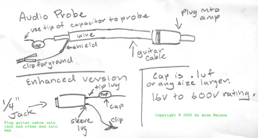 ]
]
Now you can use the tip of the capacitor to probe around the circuit. You can hear how the circuit works by touching different places in the circuit. Start from the input of your stompbox and work your way through the circuit. Follow the signal path to see where your problem lies.
You can plug your guitar into the circuit and have someone else strum it while you probe OR you can use a signal generator or a keyboard or a CD player etc.... to send signal into the circuit. You can hear the effect change the tone of the input signal.
This simple technique can alert you to cold solder joints, if you hear audio before a joint, then none right after, it's probably a cold solder joint. You can hear how a transistor is amplifying the audio. There is a lot you can learn by probing around the circuit!
I have debugged all my circuits using a combination of the above. Once you get used to using the Audio Probe, debugging a circuit becomes pretty easy.
There's a lot to be learned from the online forums. For instance, there was a thread on the Fender Blender and transistor voltages:
| Emitter | Base | Collector | |
|---|---|---|---|
| Q1 | 0.03v | 0.56v | 2.69v |
| Q2 | 2.10v | 2.67v | 3.93v |
| Q3 | 1.89v | 2.53v | 1.96v |
| Q4 | 0.00v | 0.18v | 3.80v |
| Q5 | 0.00v | 0.21v | 3.70v |
As usual R.G. Keen had an excellent analysis of the above information: Here's what your voltages say about each transistor.
Remember that for an NPN silicon transistor to be working as a linear amplifier, it MUST have its base higher than its emitter by about one silicon diode drop, 0.5 to 0.7V, and the collector must be higher than either base or emitter. The collector-to-emitter voltage is the size of the negative half signal swing, and the power-to-collector voltage is the size of the positive half signal swing.
>Q1 E-0.15 B-0.70 C-3.22
Base is 0.55 higher than emitter, collector a few volts higher than either one, and room to swing up and down on the collector - this one looks OK. We could tell how much current is flowing because the emitter to ground voltage must flow through the 15K emitter resistor, so the current is 0.15V/15K or 10uA. Looks all right.
>Q2 E-2.66 B-3.24 C-7.75
This one has its collector tied to the + supply, so its collector is equal to the battery voltage (and your second battery is getting near end of life, too ;-).
The base is 3.24-2.66= 0.58V more positive than the emitter, the collector to emitter is 7.75-2.66V = 5.09V so there's room for a signal to swing. It can swing -2.66V before it clips, and more than that positive, so this one is OK, too.
>Q3 E-3.95 B-4.63 C-3.99
Hmmmm.... base is 0.68V higher than the emitter, within the range of operation, but higher than its brothers under similar conditions. That indicates a lot of current through the base-emitter. Further, we see that the collector is only 40mv higher than the emitter - not good! This one is probably saturated, so no signal will come through. I'd bet that either the R11 150K resistor is open (bad solder joint, open PCB trace, broken or wrong value resistor) or there is DC coming in through what should be an open circuit at C5 0.1uF - either a solder short, shorted capacitor or some other such condition. Temporarily unsolder one of C5's leads and bend it up out of the board. If this fixes it, at least c5 is bad. If not, you have a problem with either R11 or a bad transistor.
>Q4 E-0.00 B-0.27 C-7.73
Ack! Another problem. Base is not at least 0.5V higher than the emitter. That means no current flows, and we see that this is true, because the emitter and collector are at ground and power supply respectively , indicating no current flow through the resistors. This one's not getting enough bias on its base. I'd guess that one of the diodes or associated resistors (R15, R16) has a solder short to ground as a first try.
>Q5 E-0.00 B-0.44 C-7.29
And another one. Base only 0.44V, no voltage drop across the emitter or collector resistors, so no current is flowing. Something is not letting enough bias get to the base. There is a solder short/wrong value resistor/something else with R28/R26/C13
Some other points from R.G. about op amps:
For an opamp to be working as a linear amplfier, both the inverting and noninverting inputs and the output pin must be within a few millivolts of the voltage on the noninverting input.